-40%
Development System for 80/100-pin PIC, w/ 87K22: EasyPIC PRO v7
$ 57.55
- Description
- Size Guide
Description
Development System for 80/100-pin PIC, w/ 87K22: EasyPIC PRO v7MIKROE-995
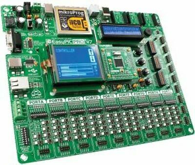
The EasyPIC PRO v7 board is a development board for high-pincount Microchip PIC microcontrollers. It comes with a PIC18F87K22 on a plug-in CPU module.
The board contains many on-board modules for all kinds of development. These include an Ethernet connector, USB device connector, RS232, USB-UART, piezo buzzer, and I2C EEPROM. There also are sockets for adding a GLCD with Touch Panel, 2×16-character LCD, DS1820 digital temperature sensor, and LM35 analog temperature sensor. See the option selectors at the bottom of this page.
The picture shows a GLCD and 16×2 alphanumeric LCD installed for illustration purposes only.
Note:
Use of the Ethernet port requires a microcontroller with Ethernet capability, such as the
PIC18F87J60
. Use of the USB Device connector requires a microcontroller with USB capability, such as the
PIC18F87J50
.
The board has three mikroBUS sockets for adding plug-and-play Click expansion modules.
The board features nine Input/Output PORT groups with IDC10 headers, buttons and LEDs.
No external programming hardware is required, for the board contains a built-in mikroProg fast USB 2.0 programmer and hardware debugger. The board also has an RJ12 ICD connector if you want to use your own PIC programmer instead.
Microchip PIC Development Board Features
Feature
CPU Module
PIC18F87K22 microcontroller has 128KB program memory, 3862 bytes RAM and operates up to
16 MIPS.
Module can be replaced with one containing a different CPU. The board supports 146 different CPUs.
Dual power supply
Board supports both 3.3V and 5V microcontrollers. It can be powered over USB cable or via an external power supply (barrel connector or screw terminals).
mikroProg
The on-board mikroProg in-circuit debugger/programmer supports over 250 Microchip PIC microcontrollers. It allows you to program the microcontroller on the board via USB cable.
ICD2/ICD3 connector
You can use your own external PIC programmer/debugger via this RJ12 jack.
USB device connector
When using a microcontroller that supports USB, you can connect the board to a PC via USB 2.0.
mikroBUS sockets
Three mikroBUS sockets allow you to use plug-and-play
Click Boards
to add peripheral functions.
Reset button
High-quality reset button and circuit ensures stable reset operation.
RS232 connector
You can implement UART communication through the DB9 RS232 connector.
USB-UART connector
The on-board FTDI USB-UART chip allows you to connect the board to a PC or other device via a virtual serial port.
Ethernet connector
When using a microcontroller that supports Ethernet, you can connect the board to a network via the RJ45 jack.
Piezo buzzer
The piezo buzzer can be connected to two digital output pins, one of which is the PWM output.
I2C EEPROM
You can store up to 8x256 bytes of configuration or other data into the on-board 24AA01 Serial EEPROM.
GLCD support
You can place a Graphical 128×64 display on the board and hold it in place with the spacers provided. The board has touch panel and backlight controllers as well. A potentiometer allows you to adjust contrast.
GLCD not included.
Alphanumeric LCD support
You can connect a 2-line by 16-character LCD on the board and secure it with the provided spacers. A potentiometer allows you to adjust contrast.
2×16 LCD not included.
ADC potentiometers
You can simulate analog inputs using two on-board potentiometers. Jumpers allow you to set which input pins they are connected to.
Temperature sensor support
The board has sockets for installing a DS1820 digital temperature sensor and an LM35 analog temperature sensor.
Neither is included.
Tri-state DIP switches
Three-position DIP switches allow you to enable a 4K7 pull-up or pull-down resistor on any desired port pin.
Push buttons & LEDs
Up to eight buttons and LEDs on each input/output group enable you to have digital inputs on each port pin. There are 69 buttons & LEDs in total.
Button press level
Three-position DIP switches allow you to pull up or pull down the buttons in each input/output group.
Port headers
Two male IDC10 port headers are available for each input/output group — one row of headers on the bottom edge, one row on the right edge of the board.
Oscilloscope GND pins
Three GND pins are available on the board for easy connection to GND reference when using oscilloscope probes.
Software Examples
The included DVD-ROM contains the following example software, both as ready-to-load compiled code and as source code written in C, BASIC and Pascal. The source codes provide detailed explanatory comments. Note that some demos require optional hardware like LCDs and sensors.
ADC library demo, displaying results on PORTC.
Button press demo, toggles LEDs on PORTD when button on PORTB is pressed.
Simple I2C demo, writing one byte on 24C02 EEPROM then reading it and displaying on PORTB.
Advanced I2C demo, initializing, writing to and reading 24AA01 EEPROM, displaying on LCD.
HTTP utils mini-library demo, creates a private web zone with authentication, and other functions.
Ethernet library demo, LCD clock that gets date and time from internet via SNTP, with embedded web server to set preferences.
HTTP demo using Ethernet library, responds to ATP, ICMP, UDP, HTTP requests.
GLCD library demo, init and clear, displaying an image or shapes, text handling.
Alphanumeric LCD library demo, writes text and scrolls it.
LED curtain effect demo.
LED blinking effect demo.
Example of using LM35 analog temperature sensor, displays on LCD.
Demonstration of DS18x20 digital temperature sensor, prints results on LCD.
Demonstration of using sound library to play tones on the piezo buzzer.
Three Touch Panel demos.
Demonstration of UART libraries, data received via RS232 are echoed back.
Demonstration of USB-UART, data received are echoed back.
Two HID demos (interrupt-based and polling), establish connection with HID terminal on PC. Characters typed on the PC are echoed back.
