-40%
Ready for XMEGA Proto Board, ATxmega128A1, USB-UART Bootloader
$ 7.91
- Description
- Size Guide
Description
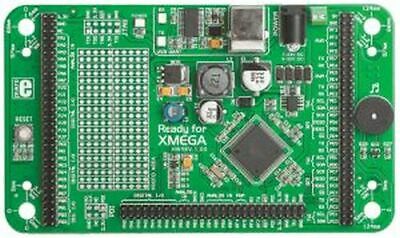
Ready for XMEGA Proto Board, ATxmega128A1, USB-UART BootloaderMIKROE-793
The Ready for XMEGA Board is a great solution for fast and simple development of various microcontroller applications. It comes with an ATxmega128A1 MCU soldered on board. The ATxmega128A1 is preprogrammed with a UART bootloader, so you don't have to use external programmers to program the microcontroller. The board contains header pins for all available microcontroller ports, grouped according to function and marked clearly on the silkscreen. It also contains a USB-UART module, prototyping area and a power supply circuit. An optional white plastic case is available so you can turn your XMEGA project into a final product.
There are pads on board for installing a 2×5-pin JTAG connector (mkII) or a 2×3-pin PDI connector in case you want to use an external programmer. The board measures
14 × 8.2 cm
(5.51 × 3.23").
Atmel XMEGA Board Features
ATxmega128A1 microcontroller
Up to 32 MIPS Operation
8/16-bit architecture
128KB of Flash memory
8KB of SRAM memory
2048 Bytes of EEPROM
78 I/O pins
32 kHz RTC
UART, SPI, ADC, etc.
Three power options
You can apply power to the board using the provided USB cable, which provides more than enough current for the MCU and every on-board module. If you want to use an external power supply, there is both a barrel connector and screw terminals to which you can supply
7-32V AC
or
9-32V DC.
Use only one method at a time.
USB-UART
An FTDI virtual serial port driver chip allows you to communicate with a PC or other UART device using a USB-UART connection. RX and TX LEDs indication communication status.
Programming with bootloader
For programming the microcontroller, you can use a bootloader program which is pre-installed in the MCU memory. To transfer a .hex file from a PC to the MCU, you can use the free mikroBootloader application. The board has a USB connector and ships with a cable to connect to your PC.
Programming with external programmer/debugger
In case you want to remove the USB bootloader, need to re-install it, or want to perform in-circuit debugging, the board has pads where you can install a 2×5-pin JTAG header. The board also has pads where you can install a 2×3-pin PDI header for using an external programmer. Pins are provided for both headers; you must solder them yourself.
Port headers
Each MCU pin is available for further connections through on-board connection headers. Each line is available on two header pins. Pins are grouped according to function, and every pin name and function is printed on the silkscreen so you won't need to keep checking the datasheet to know which pin does what.
Protoyping area
The prototype area allows you to expand your XMEGA Ready board with additional functions by placing your own components into available soldering pads. The pads are arranged in standard 100mil spacing. There are 20 connected lines on each half of the area (thus 40 lines in all) with five soldering pads for each line.
Piezo buzzer
The piezo buzzer on the board can be used during debugging or to provide audio signals in your application. The buzzer's resonant frequency is
3.8 kHz.
It can generate tones between
20 Hz
and
20 kHz,
though best performance is between
2 kHz
and
4 kHz.
Optional plastic enclosure
The board has mounting holes for placing it into a plastic enclosure which is available as an option. The enclosure exposes the USB port and the power barrel connector. The picture to the right shows what the enclosed system looks like.
Software Examples
The included DVD-ROM contains the following example software, both as ready-to-load compiled code and as source code written in C, BASIC and Pascal. The source codes provide detailed explanatory comments.
Demonstration of EEPROM library functions. Writes data then reads it out to UARTC0.
Demonstration of Flash MCU library.
Example of turning on/off LEDs connected to nine different ports (provide your own LEDs).
Demonstration of using sound library to play tones on the piezo buzzer.
Demonstration of USB-UART module. Program echoes back text sent from PC COM port.
Package Contents
Ready for XMEGA Board
USB cable
DVD-ROM with documentation and code examples
Atmel XMEGA Board Resources
Ready for XMEGA User Manual
Ready for XMEGA Schematic
Ready for XMEGA Software Examples
mikroBootloader application for ATxmega128A1
(Windows and Linux)
mikroBootloader for ATxmega128A1 User Manual
Timer Calculator Application
which generates AVR code for setting up MCU timers easily
